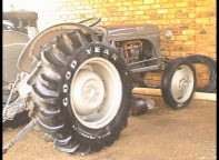
OPERATIONAL INSTRUCTIONS for the FERGUSON TE-F 20 Tractor (Vaaljapie) ....... WARNING Keep a new tractor on light work for fifty hours.

WARNING
Keep a tractor on light work for fifty hours.
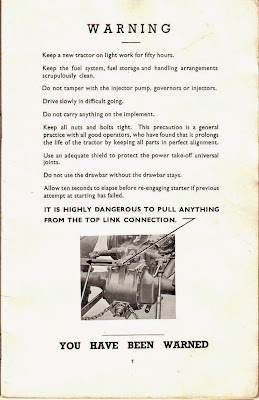
Keep the fuel system, fuel storage and handling arrangements scrupulously clean. Do not tamper with the injector pump, governors or injectors. Drive slowly in difficult going. Do not carry anything on the implement. Keep all nuts and bolts tight. This precaution is a general practice with all good operators, who have found that it prolongs the life of the tractor by keeping all parts in perfect alignment. Use an adequate shield to protect the power take-off universal joints. Do not use the draw bar without the drawbar stays. Allow ten seconds to elapse before re-engaging starter if previous attempt at starting has failed.
IT IS HIGHLY DANGEROUS TO PULL ANYTHING FROM THE TOP LINK CONNECTION

YOU HAVE BEEN WARNED

WARNING AGAINST OVERLOADING
The third gear should not be used with any implement which operates underneath the ground such as a plough, cultivator, etc.
The hydraulic system is designed to operate perfectly in first or second gear but it will not operate perfectly in third gear.
The third gear is too fast for normal implement use. Implements such as ploughs and cultivators, which operate underneath the ground, and which are liable to catch on obstructions, are not designed to stand stresses above 3 m.p.h. (5.6 k.p.h.). It is a fallacy to think that operating in third gear will save the tractor and save fuel for normal work. This gear for normal work would cause overloading, and overloading is disastrous to the life of a tractor.
The third gear is meant to be used for light work only and for implements which operate above the ground, such as a light roller.
A SIMPLE TEST OF OVERLOADING
With the tractor in motion set the throttle lever about half way open. Then quickly flick the throttle fully open. If the tractor speeds up rapidly the engine is not overloaded—if slowly, the engine is overloaded. These remarks apply to any tractor. The overloading should be remedied at once to avoid serious damage.
When operating up a steep hill the above test might indicate overloading. This is not harmful as it is compensated for when coming downhill.
It is continuous overloading that must be avoided.
OPERATIONAL SECTION
This section describes the principal tractor controls, how they are used and how the engine is started in varying climatic conditions.
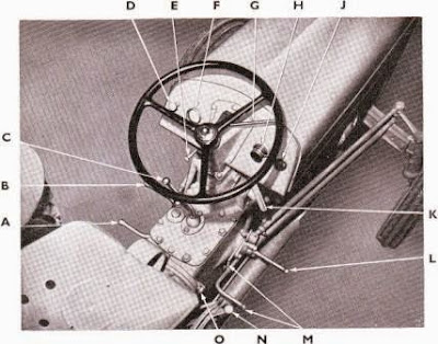
A. CLUTCH PEDAL.
B. FOOT REST.
C. GEAR SELECTOR LEVER.
D. PRE-HEATER CONTROL SWITCH.
L. FOOT REST
E. FUEL CUT-OFF CONTROL.
M. COMBINED BRAKE PEDAL
F. OIL PRESSURE GAUGE. WITH PARKING LATCH.
G. HAND THROTTLE LEVER.
N. HYDRAULIC CONTROL LEVER.
H. KIGASS INJECTOR PUMP.
J. AMMETER.
K. DECOMPRESSION LEVER— REAR.
0. STARTER SWITCH SAFETY BUTTON.
CONTROLS & INSTRUMENTS (Figs 1 & 2)
Gear Selector Lever
Lift lever for selection of reverse gear or for operation of electric starter in conjunction with safety button.
Pre-heater Control Switch
Use in conjunction with Kigass injector pump and hold out to operate.
Fuel Cut-off Control
Pull out to stop engine.
Excess Fuel Device
Press operating button before starting up (See Fig 11)
Oil Pressure Gauge
Normal pressure : 40-60 lb./sq.inch (2:8-4:2 kg./sq.cm)
Hand Throttle Control
Move clockwise to increase engine speed.
Kigass Injector Pump
Unscrew and pull out knob, then push in sharply to inject furl spray into the manifold. Screw knob in to secure.
Ammeter
Rate of charge depends on state of batteries.
Decompression Lever Three positions :-
UP - allowing full compression to all four cylinders.
INTERMEDIATE - located by ball catch - relieving compression from three cylinders.
DOWN - relieving compression from all four cylinders.
Combined Brake Pedal
Pressure on this pedal operates brakes on both rear wheels. Ratchet can be engaged for parking. Independent Brake Pedals Pressure on either pedal on appropriate wheel only, to assist reduction of turning circle.
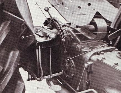
KEY TO FIG 2
A. ADJUSTABLE STOP
B. HYDRAULIC PUMP CONTROL LEVER
C. CONTROL LEVER QUADRANT
D. HYDRAULIC MECHANISM AND TRANSMISSION OIL DIPSTICK
E. STARTER SPRING LOADED SAFETY STOP
F. INDEPENDANT BRAKE PEDAL (R.H.)
G. BATTERY INSPECTION PLATE.
Hydraulic Control Lever
When hydraulic pump is in operation, rearward movement of lever raises linkage, forward movement allows it to drop under its own weight.
Starter Switch Safety Button
This must be pressed while gear selector lever is moved forward to operate electric starter. Automatic return when gear lever is moved back to neutral position.
COLD STARTING EQUIPMENT
The object of this system is to provide pre-heating and priming of the inlet manifold and combustion chambers prior to starting in temperatures below 32ºF (0ºC). An atomised fuel spray is injected into the air inlet manifold by operating the Kigass injector pump located on the instrument panel. The spray impinges on to a heater coil screwed into the manifold, providing a warm fuel vapour to assist firing.

The Kigass filter (see Fig 3) should regularly be dismantled by unscrewing lever type cap and the filter gauze removed and cleaned.
ENGINE STARTING PROCEDURE (Figs 1 and 4)
IMPORTANT
Disengagement of the starter pinion is automatic. The gear lever must be returned to the neutral position as soon as the engine fires. If the engine fails to run after firing, do not immediately jab the starter into re-engagement. Always wait at least ten seconds if previous starting attempt has failed.
Before attempting to start the engine, ensure that:-
(a) There is sufficient fuel in the tank.
(b) That all fuel line cocks are open and cut-off control is in starting position.
(c) The clutch pedal is depressed.
(d) The brake is 'on' and the ratchet engaged.
Warm weather, above 50ºF (10ºC)
1. Ensure that the decompression lever is in 'up' position to give full compression for all four cylinders.
2. Depress the excess fuel device located on the injector pump.
3. Move the hand throttle lever to the half-open position.
4. Operate the starter.
Cool weather, 32ºF-50ºF (0ºC-10ºC)
1. Ensure that the decompression lever is in the 'down' position to relieve compression from all four cylinders.
2. Depress the excess fuel device.
3. Move the hand throttle lever to the half-open position.
4. Operate the starter for two seconds, then, still allowing it to remain in operation, move the decompression lever to the intermediate position, giving pressure relief on three cylinders.
5. Immediately the engine fires, move the decompression lever up to 'full compression'.
6. As soon as all four cylinders have fired, return the gear lever to 'neutral' and set the hand throttle lever at just above 'idling' position to warm up the engine.
Cold weather, below 32ºF (0ºC)
Warming up (before starting)
1. Set the hand throttle lever in the half-open position.
2. Pull out fully the fuel cut-off control and lock in this position.
3. Set the decompression lever in the 'down' position to relieve compression from all four cylinders.
4. Hold out pre-heater control switch for 15 seconds to allow the coil to become hot, then, continuing to hold out the switch, give ONE full charge only with the Kigass injector pump, operating sharply to ensure that the spray is fine enough to be ignited.
5. Operate the starter for 10 seconds to allow the hot vapour to be drawn into the engine.
6. Release pre-heater control switch and disengage starter.
NOTE : If the batteries have become discharged, current should be conserved for starting by turning the engine by hand during the warming-up period. This is not difficult, as the engine is fully decompressed. Normally, an additional person is required to use the starting handle, but the procedure can, if necessary, be carried out by the driver alone if the heater coil switch is held out by means of a wedge. The wedge must be removed immediately after the warming-up cycle to avoid further drain on the batteries.

KEY TO FIG 4
A. PRE-HEATER CONTROL SWITCH
B. THROTTLE LEVER
C. KIGASS INJECTOR PUMP
D. ANNETER
E. DECOMPRESSION LEVER REAR
F. FUEL CUT-OFF CONTROL
G. GEAR SELECTOR LEVER
7. Move the decompression lever up to the 'full compression' position.
8. Release the fuel cut-off control.
9. Depress the excess fuel device.
10. Give approximately HALF stroke with the Kigass injector pump.
11. Pull out pre-heater control switch.
12. Operate the starter for ten seconds.
13. As soon as the engine starts, release the heater switch, return the gear lever to 'neutral' position and set the hand throttle lever at just above 'idling' position to warm up engine.
NOTE: If the engine does not start within 10 seconds, do not continue the attempt to start, but five a further warming-up as previously described.
N.B. - The Kigass pump must be screwed back securely after use.
TO STOP THE ENGINE
Pull the fuel cut-off control under left-hand side of instrument panel, shown in Fig 4. In cases of emergency only should engine be stopped by operating the decompression lever or by turning off any of the fuel taps.
BEFORE STARTING WORK
Check that engine oil pressure is correct. Ensure that there is an ample fuel supply in the tank for the work in hand.


WARNING
Keep a tractor on light work for fifty hours.

Keep the fuel system, fuel storage and handling arrangements scrupulously clean. Do not tamper with the injector pump, governors or injectors. Drive slowly in difficult going. Do not carry anything on the implement. Keep all nuts and bolts tight. This precaution is a general practice with all good operators, who have found that it prolongs the life of the tractor by keeping all parts in perfect alignment. Use an adequate shield to protect the power take-off universal joints. Do not use the draw bar without the drawbar stays. Allow ten seconds to elapse before re-engaging starter if previous attempt at starting has failed.
IT IS HIGHLY DANGEROUS TO PULL ANYTHING FROM THE TOP LINK CONNECTION

YOU HAVE BEEN WARNED
WARNING AGAINST OVERLOADING
The third gear should not be used with any implement which operates underneath the ground such as a plough, cultivator, etc.
The hydraulic system is designed to operate perfectly in first or second gear but it will not operate perfectly in third gear.
The third gear is too fast for normal implement use. Implements such as ploughs and cultivators, which operate underneath the ground, and which are liable to catch on obstructions, are not designed to stand stresses above 3 m.p.h. (5.6 k.p.h.). It is a fallacy to think that operating in third gear will save the tractor and save fuel for normal work. This gear for normal work would cause overloading, and overloading is disastrous to the life of a tractor.
The third gear is meant to be used for light work only and for implements which operate above the ground, such as a light roller.
A SIMPLE TEST OF OVERLOADING
With the tractor in motion set the throttle lever about half way open. Then quickly flick the throttle fully open. If the tractor speeds up rapidly the engine is not overloaded—if slowly, the engine is overloaded. These remarks apply to any tractor. The overloading should be remedied at once to avoid serious damage.
When operating up a steep hill the above test might indicate overloading. This is not harmful as it is compensated for when coming downhill.
It is continuous overloading that must be avoided.
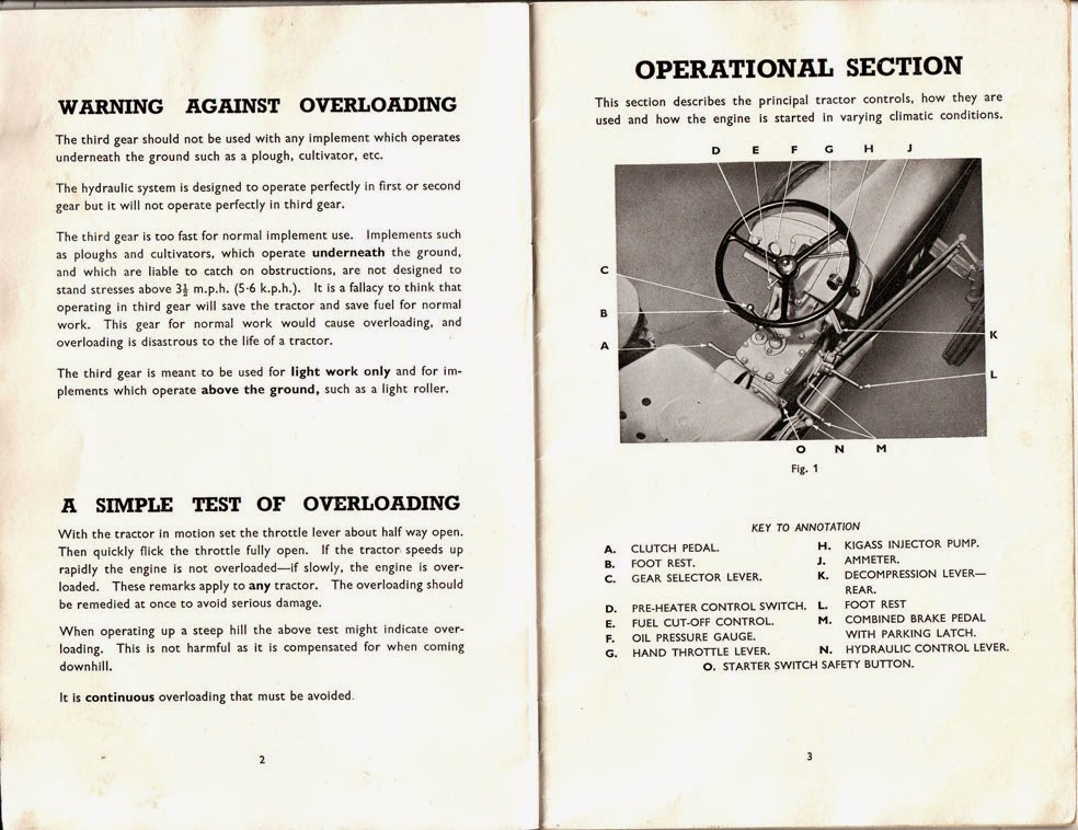
OPERATIONAL SECTION
This section describes the principal tractor controls, how they are used and how the engine is started in varying climatic conditions.

Fig. I
A. CLUTCH PEDAL.
B. FOOT REST.
C. GEAR SELECTOR LEVER.
D. PRE-HEATER CONTROL SWITCH.
L. FOOT REST
E. FUEL CUT-OFF CONTROL.
M. COMBINED BRAKE PEDAL
F. OIL PRESSURE GAUGE. WITH PARKING LATCH.
G. HAND THROTTLE LEVER.
N. HYDRAULIC CONTROL LEVER.
H. KIGASS INJECTOR PUMP.
J. AMMETER.
K. DECOMPRESSION LEVER— REAR.
0. STARTER SWITCH SAFETY BUTTON.
CONTROLS & INSTRUMENTS (Figs 1 & 2)
Gear Selector Lever
Lift lever for selection of reverse gear or for operation of electric starter in conjunction with safety button.
Pre-heater Control Switch
Use in conjunction with Kigass injector pump and hold out to operate.
Fuel Cut-off Control
Pull out to stop engine.
Excess Fuel Device
Press operating button before starting up (See Fig 11)
Oil Pressure Gauge
Normal pressure : 40-60 lb./sq.inch (2:8-4:2 kg./sq.cm)
Hand Throttle Control
Move clockwise to increase engine speed.
Kigass Injector Pump
Unscrew and pull out knob, then push in sharply to inject furl spray into the manifold. Screw knob in to secure.
Ammeter
Rate of charge depends on state of batteries.
Decompression Lever Three positions :-
UP - allowing full compression to all four cylinders.
INTERMEDIATE - located by ball catch - relieving compression from three cylinders.
DOWN - relieving compression from all four cylinders.
Combined Brake Pedal
Pressure on this pedal operates brakes on both rear wheels. Ratchet can be engaged for parking. Independent Brake Pedals Pressure on either pedal on appropriate wheel only, to assist reduction of turning circle.

Fig 2
KEY TO FIG 2
A. ADJUSTABLE STOP
B. HYDRAULIC PUMP CONTROL LEVER
C. CONTROL LEVER QUADRANT
D. HYDRAULIC MECHANISM AND TRANSMISSION OIL DIPSTICK
E. STARTER SPRING LOADED SAFETY STOP
F. INDEPENDANT BRAKE PEDAL (R.H.)
G. BATTERY INSPECTION PLATE.
Hydraulic Control Lever
When hydraulic pump is in operation, rearward movement of lever raises linkage, forward movement allows it to drop under its own weight.
Starter Switch Safety Button
This must be pressed while gear selector lever is moved forward to operate electric starter. Automatic return when gear lever is moved back to neutral position.
COLD STARTING EQUIPMENT
The object of this system is to provide pre-heating and priming of the inlet manifold and combustion chambers prior to starting in temperatures below 32ºF (0ºC). An atomised fuel spray is injected into the air inlet manifold by operating the Kigass injector pump located on the instrument panel. The spray impinges on to a heater coil screwed into the manifold, providing a warm fuel vapour to assist firing.

Fig 3
The Kigass filter (see Fig 3) should regularly be dismantled by unscrewing lever type cap and the filter gauze removed and cleaned.
ENGINE STARTING PROCEDURE (Figs 1 and 4)
IMPORTANT
Disengagement of the starter pinion is automatic. The gear lever must be returned to the neutral position as soon as the engine fires. If the engine fails to run after firing, do not immediately jab the starter into re-engagement. Always wait at least ten seconds if previous starting attempt has failed.
Before attempting to start the engine, ensure that:-
(a) There is sufficient fuel in the tank.
(b) That all fuel line cocks are open and cut-off control is in starting position.
(c) The clutch pedal is depressed.
(d) The brake is 'on' and the ratchet engaged.
Warm weather, above 50ºF (10ºC)
1. Ensure that the decompression lever is in 'up' position to give full compression for all four cylinders.
2. Depress the excess fuel device located on the injector pump.
3. Move the hand throttle lever to the half-open position.
4. Operate the starter.
Cool weather, 32ºF-50ºF (0ºC-10ºC)
1. Ensure that the decompression lever is in the 'down' position to relieve compression from all four cylinders.
2. Depress the excess fuel device.
3. Move the hand throttle lever to the half-open position.
4. Operate the starter for two seconds, then, still allowing it to remain in operation, move the decompression lever to the intermediate position, giving pressure relief on three cylinders.
5. Immediately the engine fires, move the decompression lever up to 'full compression'.
6. As soon as all four cylinders have fired, return the gear lever to 'neutral' and set the hand throttle lever at just above 'idling' position to warm up the engine.
Cold weather, below 32ºF (0ºC)
Warming up (before starting)
1. Set the hand throttle lever in the half-open position.
2. Pull out fully the fuel cut-off control and lock in this position.
3. Set the decompression lever in the 'down' position to relieve compression from all four cylinders.
4. Hold out pre-heater control switch for 15 seconds to allow the coil to become hot, then, continuing to hold out the switch, give ONE full charge only with the Kigass injector pump, operating sharply to ensure that the spray is fine enough to be ignited.
5. Operate the starter for 10 seconds to allow the hot vapour to be drawn into the engine.
6. Release pre-heater control switch and disengage starter.
NOTE : If the batteries have become discharged, current should be conserved for starting by turning the engine by hand during the warming-up period. This is not difficult, as the engine is fully decompressed. Normally, an additional person is required to use the starting handle, but the procedure can, if necessary, be carried out by the driver alone if the heater coil switch is held out by means of a wedge. The wedge must be removed immediately after the warming-up cycle to avoid further drain on the batteries.

Fig 4
KEY TO FIG 4
A. PRE-HEATER CONTROL SWITCH
B. THROTTLE LEVER
C. KIGASS INJECTOR PUMP
D. ANNETER
E. DECOMPRESSION LEVER REAR
F. FUEL CUT-OFF CONTROL
G. GEAR SELECTOR LEVER
7. Move the decompression lever up to the 'full compression' position.
8. Release the fuel cut-off control.
9. Depress the excess fuel device.
10. Give approximately HALF stroke with the Kigass injector pump.
11. Pull out pre-heater control switch.
12. Operate the starter for ten seconds.
13. As soon as the engine starts, release the heater switch, return the gear lever to 'neutral' position and set the hand throttle lever at just above 'idling' position to warm up engine.
NOTE: If the engine does not start within 10 seconds, do not continue the attempt to start, but five a further warming-up as previously described.
N.B. - The Kigass pump must be screwed back securely after use.
TO STOP THE ENGINE
Pull the fuel cut-off control under left-hand side of instrument panel, shown in Fig 4. In cases of emergency only should engine be stopped by operating the decompression lever or by turning off any of the fuel taps.
BEFORE STARTING WORK
Check that engine oil pressure is correct. Ensure that there is an ample fuel supply in the tank for the work in hand.


::


